
Routine fluid analysis is a critical part of any preventive maintenance program. Not only do the results indicate what condition the fluid is in, they also provide an early warning of system or equipment problems that can eventually shut down the process.
WHEN TO TEST
New System/New Fluid – Thermal fluids seldom go bad without help — 95% of fluid degradation is caused by poor design, operating errors or malfunctions. These problems can usually be detected early on in new systems if the fluid is tested within the first 6 to 9 months of start-up.
Existing System/New Fluid – A sample should be taken 1 to 2 weeks after start-up to determine how much of the old fluid is still in the system.
Regular Testing – Unless there is an issue that needs to be monitored more frequently, systems should be sampled once a year.
Not only do the results of routine fluid analysis indicate what condition the fluid is in, they also provide an early warning of system problems that can shut down the process.
SAMPLING
We can’t provide you with the right corrective actions if we’re analyzing the wrong data. Following these guidelines will ensure that the sample you send us is exactly the same composition as what is circulating in your system.
Where – Samples should always be taken where the fluid is hot and flowing. Blowdown valves on pump-suction strainers or anywhere near the pump suction will provide the lowest temperature/lowest pressure sample point in the system. Samples should not be taken from the expansion tank or any dead legs — the sample may be easier to handle but will not be representative of what is actually circulating.
Temperature – The optimum sampling range is between 180° to 230°F. The minimum temperature ensures that no components have solidified out of the sample and the maximum temperature ensures that the glass sample jar will not break. If you’re not scheduled to cool the system down in the near future, then install 18 to 24 in. of copper tubing on the sample port to cool the sample.
How – The sample must flow directly into the sample jar. Do NOT catch the sample in a metal bucket and allow it to cool because any carbon will settle out and remain in the bucket – remember the sample that we test has to be representative of what is actually moving in the piping.
Filling the Jar – Purge at least 1 to 2 jars of fluid through the sample line to make sure that any non-circulating solids are removed. Then fill the jar 2/3 full with sample and tighten the lid. Allow sample to cool.
Labeling and Paperwork – When the jar is cool enough to touch, fill in the required information on the label. Complete the information requested on the bottom of the Instruction sheet that is enclosed with each sample jar.
The higher the number the more oxidation has occurred. It is the most important test because acids are the raw materials for every thermal fluid system horror story such as sludged-up expansion tanks, cracked heater tubes and “black yogurt” (gelled fluid).
LABORATORY TESTING
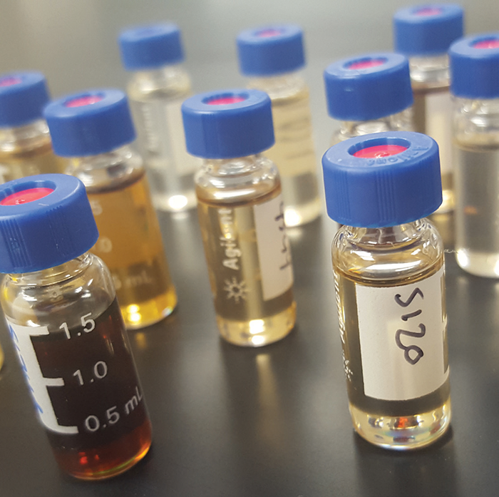
Every sample is visually inspected for carbon which is an indicator of fluid degradation. Carbon doesn’t directly affect the properties of the fluid but it can cause mechanical problems such as plugged sensors, expansion-tank sludge and piping blockages that will affect system performance.
Suspended carbon consists of the fine carbon particles (soot) that form in the heater and flow with the fluid into the sample jar. It’s a measure of the overall loading.
Sediment – If the amount of suspended carbon becomes excessive, it will settle to the bottom of the sample jar and form a layer of sediment.
Acid Number (ASTM D-664) measures the amount of acid present in the fluid which in turn is an indication of the amount of oxidation that has occurred. The higher the number the more oxidation has occurred. It is the most important test because acids are the raw materials for every thermal fluid system horror story such as sludged-up expansion tanks, cracked heater tubes and “black yogurt” (gelled fluid).
Distillation Range ASTM D-2773 uses gas chromatography to measure the boiling points in ˚F of 5%, 10%, 20% etcetera up to 95% of the sample. Every thermal fluid contains multiple components each of which boils at a specific temperature which gives it a unique pattern which will change predictably as the fluid degrades. The difference in temperature between the sample and a new fluid baseline are averaged and shown as “% Low Boilers” and ”% High Boilers.”
Test results outside of the expected degradation pattern indicates that some other fluid is present.
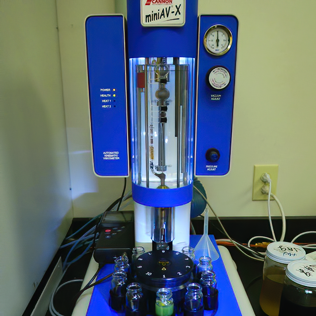
Viscosity – ASTM D-445 identifies how “thick” or viscous the fluid is. The sample viscosity will increase due to degradation caused by high acid number (oxidation) and will decrease due to overheating.
 ANALYZING THE RESULTS
Comparing the used fluid to new fluid is usually sufficient to determine whether the fluid has degraded enough to require change out. However, as noted above, 95% of fluid degradation is caused by external forces. Unless the equipment or process conditions that are causing accelerated degradation are corrected, fluid change out could become an annual routine.
Properly analyzed and interpreted, the test results can provide the information necessary to identify and correct these undetected problems. Even more valuable are the trends that are evident when samples have been taken at routine intervals. Knowledge of the equipment is also necessary to properly interpret the results and identify the source of the degradation.
Contact Ed Cass, Paratherm Technology Manager — Heat Transfer Fluids, at 800.222.3611 or 610.941.4900, info@paratherm.com
Print this page