Monitoring Combustible and Toxic Gases in Industrial Environments
By Jonathan Espinoza, Sales Engineer
Features ipptIn survival situations the rules of three apply: three weeks without food, three days without water and three minutes without air – are all deadly. Clean air is vital for human health and must be stringently monitored in industrial environments where toxic, corrosive, asphyxiant and combustible gas hazards are common.
In food & beverage plants anhydrous ammonia is used as a refrigerant, hydrogen sulfide can accumulate in sewage systems of wastewater treatment centers and carbon monoxide from engine exhaust fumes can accumulate in fuel tank filling stations. These are all examples of toxic gas hazards that can be monitored using electrolytic sensors that we will cover in this article. Toxic gasses are all gasses that are harmful to living things. Safety is paramount, and it is absolutely necessary to monitor these gases when exposure is likely. While Fixed Gas Systems don’t directly contribute to the bottom line they do add significant value by protecting your assets and ensure onsite workers make it home safely.
Gas Detection Systems
Gas detections systems are put in place to alert workers of hazardous conditions such as toxic, corrosive and asphyxiant gas reaching harmful concentrations and combustible gas leaks reaching their lower explosive limit (LEL).
Sensidyne Fixed Gas Detection systems consist of a sensor and transmitter which is installed in a fixed location in close proximity to the potential hazard source. Transmitters remain fixed and do not require preventive maintenance, but the sensors are consumable and require periodic calibrations or replacement once the sensor has reached the end of its life. In an event of a gas leak the transmitter will provide signalling to the gas detection system, which in turn will engage sirens, horns and any automated functional actions that are integrated in the sites Distributed Control System (DCS.) As with any complex engineering system there are challenges with ensuring your system functions as intended and meets the regulatory codes within your facility. At Sensidyne our experts and engineers are professionally trained and accomplished to guide your selection to ensure your Gas Detection needs are met.
Asphyxiant and Toxic Gas Hazards: Electrolytic Sensors
An Electrolytic sensor consists of a stack of electrodes and wetted electrolyte filters. One electrode is exposed to the air and two other electrodes are encased inside surrounded by hydrophilic separators and electrolyte solution. The electrode exposed to air is called the working electrode and is optimized for an oxidation or reduction reaction to occur depending upon the target gas. These sensors are utilized to detect the presence of toxic gas and are also use to monitor oxygen levels.
Another hazard that can occur in industrial environments is asphyxiation caused by low oxygen levels. This working electrode reacts when it comes into contact with a target gas, reacts and generates a current that is linearly proportional to the fractional volume of the target gas. These sensors have a lifespan of typically two years so an inventory management system should be considered to ensure spare sensors remain viable for use. Our universal transmitters keep track of the sensor life and can be configured to send an alert when the sensor is starting to reach the end of its life. Our transmitters can also be configured to go into a fault state when the sensor requires calibration, which allows the maintenance team to plan ahead appropriately and avoid any potential unscheduled downtime.
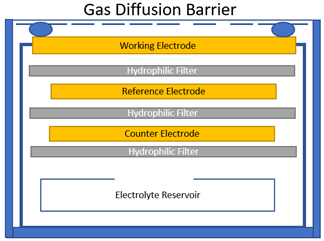
Figure 1: Electrolytic cell
Combustible Gasses and CO2: Infrared Sensors (IR)
IR sensors utilize Infrared Spectroscopy, the study of how molecules interact with infrared light to discern information about its chemical bonds. This method is commonly used in labs to analyze and determine all sorts of molecular species. This method is particularly effective with sensing the hydrocarbon gasses that are found in oil & gas plants. Another advantage IR sensors have is that they are not susceptible to being poisoned as is the case with catalytic bead sensors. IR sensors are not limited to combustible gasses however, Sensidyne carries IR sensors for CO2 gas which is inert and would not be detected with electrolytic cells or catalytic bead sensor.
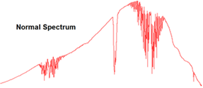
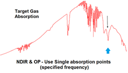
Figure 2: Infrared Spectroscopy Readings
Photoionization: Volatile Organic Compounds
The presence of volatile organic compounds (VOCs) is growing concern for industrial complexes, exposure to these hazardous substances care detrimental to human health. Photoionization is the most common technique used to sense VOCs. A photoionization detector, “PID” for short, is composed of an ultraviolet light source and sensor. Any present VOC molecule is will ionize while exposed to UV radiation. After exposure an electron is released, this free electron is detected and measured by the electronics imbedded in the sensor. Each compound has a unique “Ionization Potential (IP)” value measured in electron volts (eV). This specific IP value is used to determine the eV rating of the lamp in the sensor which will filter out any unwanted interactions form other VOCs.
Figure 3: Photoionization Detector
Combustible Gases: Catalytic Bead Sensors
Catalytic bead sensors fall under the family of gas sensors known as pellistors; this term is an amalgamation of word pellet and resistor. This technology has been around for more than half of century and originally developed for the use in mining operations. Previous to this invention by the British scientist Alan Baker, miners used canaries to determine the presence of methane in mining shafts – if the canary died, then methane was present at a toxic level (and hence the phrase “canary in a coal mine”). The sensor is composed of a heated metal oxide catalyst that will oxidize a combustible gas; the heat generated by this reaction causes a change in resistance of the element. This resistance change is proportional to the gas concentration. The operating principle has been proven to be reliable and effective although there are some caveats. Exposure to hydrogen sulfide, styrene, polymers or any substance that forms thin films under heat may poison or inhibit the sensor. When such substances are present it is best to consult with a sales engineer to assist with selecting the proper detection, in many instances an IR sensor might be needed.
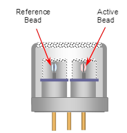
Figure 4: Catalytic Bead Sensor
Lower Explosive Limit
The Lower Explosive Limit (LEL) is the lowest concentration of combustible gas in air that is capable of producing a flame in the presence of an ignition source. It is represented by a percentage not a concentration since the LEL concentration by volume varies from gas to gas. Typically, when the LEL gas is not methane or propane, a K factor is programmed into the transmitter to tune the detector to the specific target gas. In cases where multiple combustible gases are present, the sensor should be programmed to highest K factor (the least sensitive gas) to achieve the safest configuration. It is worth noting that in this configuration the LEL% reading for the other gases will respond higher than the actual LEL concentration. The LEL varies between combustible gases, methane for example has an LEL concentration of 5% by volume in air, which the transmitter will display as 100% LEL. 0% LEL would indicate a gas concentration of 0% vol.
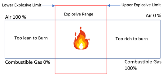
Figure 5: LEL Range
Transmitter
The transmitter interprets the output from the sensor and displays the reading which then can be communicated to the control system, typically a controller that manages alarms, strobes and functional actions. The most common output for the transmitter is analog 4-20mA, but we also offer MODBUS, HART, BacNet and relay options. The selection of your transmitter will be determined by the hazardous area classification, communication protocol and budgetary requirements. There are some transmitters such as the SensAlarm FLEX in Sensidyne’s catalog with a fully integrated with alarm/ strobe and relays as a true “Plug and Play” gas detection system.
Calibration
The procedure of calibration verifies and maximized the accuracy of the sensor by comparing the instrument to a known standard, the standard in this case will be calibration gas which we supply our customers. The process is expected to be part of your planned preventive maintenance schedule. Our sensors are calibrated at the factory but do require calibration upon arrival. The environmental conditions that the sensor is calibrated should be the same as the area in which the sensor will be stationed. Our sensors are calibrated in Florida so a sensor installed in a higher altitude city such as Denver would need to be calibrated during its commissioning to ensure accuracy. Calibration is also recommended after a high-level reading or an extended period of constant exposure to the target gas. The gas standard is typically the same as the target gas and is used at half of the sensor full range for almost all toxic gases. When it comes to combustible gases propane or methane are used as surrogates and a K factor is applied at the transmitter when the target gas is not the same, which is a mathematical correction factor.
K Factors
Both IR and Catalytic bead sensors interact with multiple combustible gases so the appropriate corrective K factor will need to be programmed onto the transmitter when the specific target gas is not used as a calibration gas standard. This means that a target gas such as Dimethyl Ether can be calibrated using methane calibration gas. A K factor list for IR and Catalytic Bead sensors can be found in the respective datasheet on our website.
Area Classification
Hazardous area classifications systems are in place to facilitate the safe use of electrical equipment in environments with the potential presence of combustible substances. The manner in which these areas are defined is dependent on the country, but the overall concept remains the same. They are mainly classified by two variables: the combustible source (Class) and the likelihood that it would be present (Division). Electronics with hazardous ratings have specific engineering controls built in to eliminate the possibility of being a source of ignition. It is imperative to know this information, failure to do so could result in unsafe conditions that could create negative consequences. Hazardous rated equipment usually comes at a higher cost. Knowing when it is acceptable to purchase a non-hazardous device will lead to savings on capital expenses.
Examples of hazardous area classifications include:
Class 1, Division 1
Class 1, Division 2
Class 2, Division 1
Class 2, Division 2
Zone 0
Zone 1
Zone 2
Sensor Placement
It’s important to understand where your target gas will likely accumulate if there is a leak. Ammonia (NH3) gas is lighter than air, so sensors for NH3 should be placed higher, heavier hydrocarbons will accumulate near the ground, so those sensors should be lower. If sensing for oxygen, these sensors should be installed in the breathing zone level. The ideal location of the sensor is a location where the highest concentration is likely to occur. A sensor placed near an entryway or ventilation exhaust will be exposed to a dilute sample while other areas increase in concentration of the target gas, this could cause an unsafe work condition.
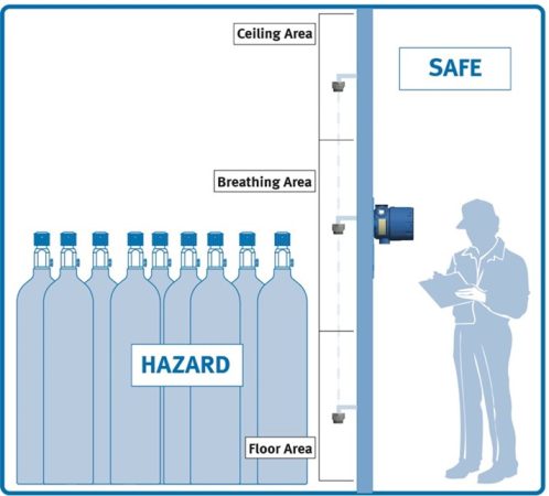
Figure 6: Remote Sensor Placement
The Combustible Sensor can be remote mounted up to 100 feet (30m) from the transmitter to the ceiling area, the breathing area, or the floor area, depending on the gas hazard.
Sample Draw
There are cases where the optimal sensor location is challenging, such as a difficult to access deep well would require a multitude of work permits and safety protocols to access. In this instance a sample draw system would be beneficial. The sample draw is essentially a gas pump skid that would draw a gas sample from one area and feed it into a fixed gas sensor installed in a safer area. These systems allow access to hard-to-reach areas and keep maintenance workers away from potential hazards. Avoiding the need for work permits and safety gear during planned maintenance since the serviceable components of would in installed in a safe area.
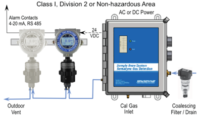
Figure 7: Sample Draw System
Expert Guidance
Selecting an optimal Fixed Gas system to meet your needs may seem like a daunting task, but our network of friendly experts and engineers are happy to assist. Please call or email your local manufacturers representative for assistance with your questions.
Author: Jonathan Espinoza, Sales Engineer
Email:jespinoza@sensidyne.com
Web: www.Sensidyne.com
Phone: 800-451-9444
Print this page