The challenge and solution: inventory management of NGLs in horizontal vessels
Mike Edwards
Features Endress+Hauser inventory management natural gas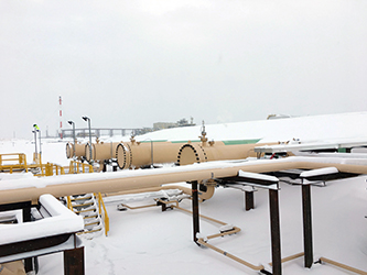 The five, buried storage tubes comprising the Tower Centralized Liquids Hub are set at a 1° slope, a function of favourable
topography that produces a five metre drop from inlet elevation to outlet.
The five, buried storage tubes comprising the Tower Centralized Liquids Hub are set at a 1° slope, a function of favourable
topography that produces a five metre drop from inlet elevation to outlet. In the Dawson Creek area of British Columbia, a large natural gas resource play has been developed by the Cutbank Ridge Partnership (CRP), a joint venture between Encana Corporation and Cutbank Dawson Gas Resources Ltd, a subsidiary of Mitsubishi Corporation.
By Gord Bill and Jason Riegert
The CRP gas is processed in three gas plants owned by Veresen Midstream Limited Partnership (VMLP), Kohlberg Kravis Roberts & Co. L.P. (KKR) and Pembina Pipeline Corporation, and the produced commodities include pipeline quality sales gas and natural gas liquids (NGLs). These NGLs are sold into pipeline out of the Tower Centralized Liquid’s Hub (TCLH), which is a central storage terminal with LACT (Lease Authority Transfer Access) and pipelined receipts from all three gas plants as well as third party truck-in.
NGL is high vapour pressure liquid comprised of mostly propane and butanes. Changes in temperature and pressure result in an expansion/ shrinkage of the liquid, so accounting for these changes in the daily and monthly balancing is critical; otherwise, it could result in serious under or over reporting of the inventory. For these facilities, the accounting procedure approved by the British Columbia Oil and Gas Commission (OGC) and the British Columbia Ministry of Finance (MOF) required VMLP to equalize:
1) the pipeline LACT sales volumes at a component level plus/minus tube inventory to,
2) the Tower hub’s receipt meters, both flowlined and trucked production and to,
3) the gas plant meters plus/minus the NGL inventory at the gas plants.
In the event of potential metering differences, the equalization would be made through the application of proration factors.
The design of this hub is different than most, instead of commonly used surface storage vessels or bullets consideration was given to multiple large diameter buried pipes in order to provide the required storage capacity of ~3,550 m3.

Measurement from the level transmitters, applied using a unique strapping table implemented in the Tankvision solution
supplied by Endress+Hauser, yields accurate inventory
(Net Standard Volume).
The Tower hub is comprised of five horizontal 1.3 x 500 m long pipes that are buried at a depth of 1.2 m and set at an angle of 1° slope. This necessitated a unique inventory measurement system that accounts for that slope, where the outlet elevation ends up five metres lower than the inlet.
In addition, each tank has an elliptical head at the inlet and a flat flange at the outlet, so the vessels are not perfectly symmetrical. Technology like free space radar measurement is usually applied in perfectly level, above-ground storage but was not suitable for this particular application.
The decision to proceed with the buried tube design was based on a number of factors including previous experience from VMLP at other sites, regulatory approval, favourable topography as well as cost. Burying the tubes achieved substantial cost savings. It was possible to apply a different design specification – CSA Z662, which is a Canadian Code that oil pipelines are typically built to instead of ASME B31.3, generally used for surface processing facilities. This meant less physical infrastructure like flare and drain systems, and lower material costs because of the simplicity of the design. The topography of the site favoured buried storage, with a natural slope that allows gravity to assist in moving NGL through the tubes and providing additional net positive suction head (NPSH) on the facility outlet pumps – reducing their size and cost as a benefit.
Selecting the optimal site and design approach for the Tower hub was just one of the challenges involved. It also required developing an effective inventory management system to provide accurate measurement and reporting of the volume in storage as part of the daily and monthly reconciliation of receipts and deliveries.
All the measurement systems have to comply with the BCOGC’s Measurement Guidelines for Upstream Operations which states a total installed measurement uncertainty of 0.5% or better for all flow meters and inventory level devices.
The metered NGL volumes leaving the three nearby gas plants as well as the TCLH’s receipt and pipeline LACT coriolis meters are pressure and temperature compensated to API 11.2.2 and GPA TP-27, thus it is necessary to perform the same adjustment to the NGL stored at the hub.
To achieve the 0.5% measurement uncertainty the storage volume would have to be determined by creating a unique strapping table and correcting the volume per API 11.2.2 and GPA TP-27. Along with the tank strapping tables, the equipment used to provide all of the information to attain the corrected volume includes:
- level transmitters
- temperature transmitters
- pressure transmitters
- density transmitters
- tank volume corrector
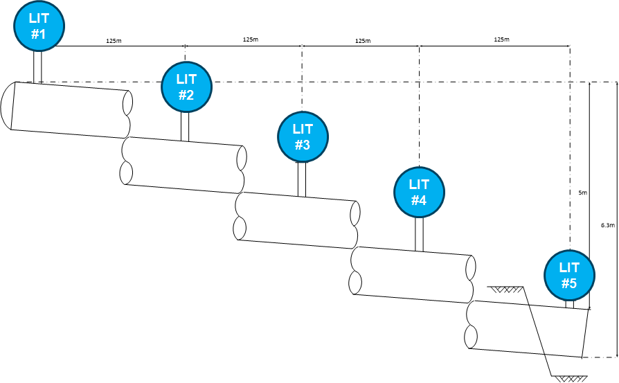
Spacing five guided wave radar transmitters 125 metres apart along the 500 metre length of each tube leaves a 50 mm overlap for comprehensive coverage of the inventory.
Measuring the NGL level in a tube that is horizontally level would be fairly simple; a single level transmitter would be all that is required.
However, the 1° slope and 500 m length of the storage tubes means the inlet elevation of each is 5 m higher than the outlet. So how exactly is level measurement performed? By utilizing five guided wave radar transmitters equally spaced 125 m apart. This approach left a 50 mm overlap between devices, giving full coverage of the tubes without any dead spots to provide the data for an observed volume reading.
There were further challenges. The process of generating the Net Standard Volume (NSV) of liquids for final accounting and reporting purposes involves multiple, sequential adjustments. A unique tank strapping table was created to provide the basis for generating an overall liquid level (or Total Observed Volume) from the transmitter data. That’s the non-pressure/temperature corrected liquid volume in the tubes. Next, factoring in various other calculations and volume correction factors as defined by the API and as required by the BCOGC, the NSV can be determined. The E+H Tankvision Inventory Management System performs this function.
Tube Strapping
Determining the strapping table in a conventional surface tank usually involves employing a surveying laser setup in the vessel. For this project, a theoretical strapping table was created during the engineering phase and had to take into account the five level transmitters, the flat flange on the outlet side and elliptical head on the inlet. In fact, five separate tables were created, with each one referenced to each of the five level transmitters and all of these tables were combined into one.
Verifying the correctness and accuracy of the theoretical table leveraged one of the required construction steps, the hydrotest. Discrepancies could arise between the theoretical table and what was actually installed because of inconsistencies in the physical construction and slope of the tubes.
During the hydrotest, a coriolis flow meter was used to measure the volume of hydrotest fluid as the tubes were being filled. E+H technicians, using a data acquisition system called Memograph, monitored the in-flowing volumes and the level measured on each of the five guided wave transmitters.
This ensured that the level from each transmitter versus volume would be known. This approach had no impact on the construction plan: one phase of construction yielded two results, hydrotest and accurate tank capacity tables.
Solution Selected The desired operational philosophy coupled with the challenges of distance (500 m) led to the choice of Rockwell Automation ControlLogix PLCs at the terminal’s inlet and outlet areas, interconnected via fibre optics. To minimize wiring costs, some of the instrumentation is wired to each of the two control system racks, one each at the inlet and outlet. In order to avoid rounding and resolution errors commonly expected with analog 4 to 20 mA technology, a digital technology, HART protocol, was used. All instruments communicate to the PLCs using HART, which is interpreted by the control system’s smart input modules. By employing HART, all measurements and calculations leverage 32- bit all-digital values. This helps to satisfy the project requirement for an installed total volumetric measurement uncertainty of 0.5% or better.
Another goal in setting up the inventory management system was to maximize system availability and minimize life-cycle operating costs.
Planners achieved this by feeding the NSV and output parameters directly into the TCLH’s control system without the need for special software installed on application servers. Tankvision interfaces with the PLC to collect the different digital measurements, leveraging the local area network based on EtherNet/ IP. Tankvision then performs the required calculations, satisfying BCOGC requirements by correcting the C3/C4+ volume to equilibrium vapour pressure and 15°C using GPA TP-27/ API MPMS 11.2 Table 54E. The results are then returned to the control system and operations over EtherNet/IP.
By employing digital and open interfaces, the inventory system dispensed with the use of custom interfaces that would be a challenge to maintain over the hub’s life cycle.
One of the life cycle and maintenance requirements was the ability to verify and document the level instruments’ performance insitu without affecting the operation of the inventory measurement system. This is achieved using E+H’s Heartbeat Technology. Heartbeat is integrated into the guided wave radar transmitters, offering insitu verification traceable to the level instruments’ original multi-point factory calibration. This distinct, documented test can be initiated from the level device display or remotely from the PLC using E+H FieldCare software. It provides technicians with a simple guided test procedure and automatically generated test protocol, with supporting documentation that validates the reliability of the device measurement.
After more than a year of operation, the measurement system has achieved its design objectives. It has proven accurate, reliable and easy to maintain. Its development shows how a challenging inventory measurement requirement can be solved through collaboration throughout the various phases (e.g. design, construction, commissioning and operation) of developing an NGL storage facility. And it shows how an energy company as operator in collaboration with a solutions provider can overcome all challenges to deliver a successful project that will serve all stakeholder interests for many years to come.
Gord Bill is with Encana Services Company Ltd. and Jason Riegert is with Endress+Hauser Canada.
Print this page