Using block valves to isolate industrial fluid systems for safer maintenance
Mike Edwards
Features Swagelok Figure 5: An integral double-block-and-bleed valve features fewer potential leak points, reduced space and weight, and simplified installation.
 Safety is the top priority in refineries and plants around the world, and many of the differing applications within them require specific considerations to best protect staff members at all times.
By Joe Bush
For example, a single fluid line’s interior pressure or flow can represent a critical hazard for technicians if they are changing a gauge or measurement device. Performing this necessary maintenance task safely requires isolating any fluid system line prior to the work, and the importance of doing so must be emphasized to and understood by all plant personnel.
The installation of double sequenced block valves has therefore become an industry standard in fluid system design, enabling technicians to bleed out an energized leg for required maintenance to be performed more safely – with zero pressure and zero flow. This article outlines best practices to successfully design two different double block valve configurations, giving operators and technicians options for enhancing safety when performing required maintenance.
Where to Isolate a Line
Industrial fluid systems are complex, with numerous locations requiring isolation when performing maintenance. Isolation is essential to protect staff members in the following areas:
* Any component requiring ongoing, regular maintenance, including valves, filters, or transmitters
* Sections of the main process pipe that may require service
* Any system, skid, or line that may require repair or replacement
* Instrumentation lines branching off the process line, including grab sampling stations, sampling systems, and areas where pressure, temperature, or flow readings are taken
* Locations where calibration fluids are used
* Sampling streams that may be switched on or off
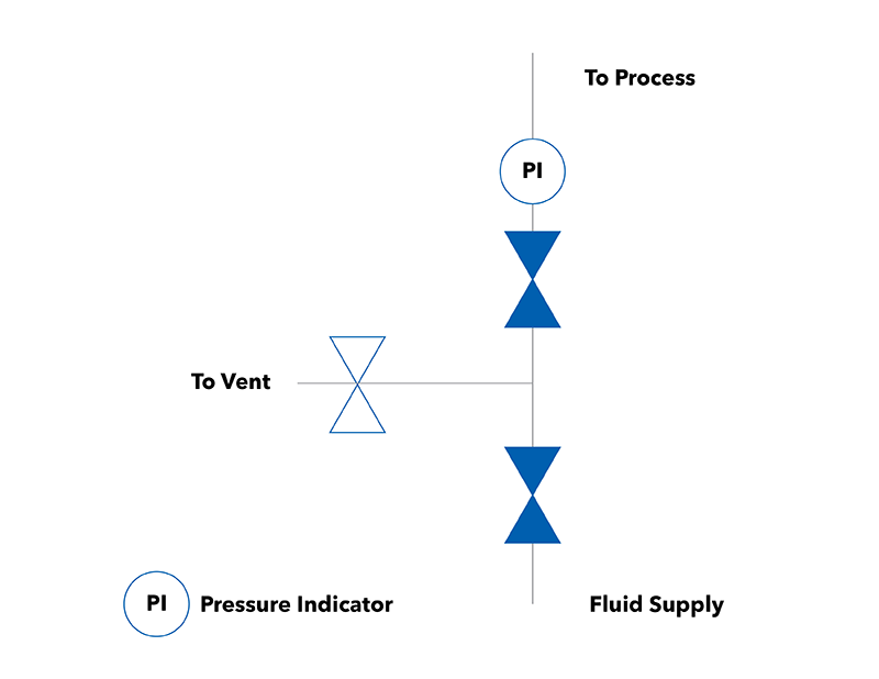
Figure 1. A typical double-block-and-bleed (DBB) configuration enables fluid system isolation for simplified, safe maintenance.
Isolation Approaches
Two common approaches have prevailed to best depressurize sections of fluid systems that require maintenance in varying applications. First, is the double-block-and-bleed (DBB) configuration, which adds a third valve between the two block valves to vent or bleed off any leaking pressure from the first block valve. The second option involves using a third valve to divert flow to a bypass loop around the section undergoing maintenance.
Here are some details engineers should know about each approach:
Double-Block-and-Bleed Configuration. The DBB configuration (Figure 1 above) is the simplest configuration for isolating a fluid system and can be configured as a single manifold unit or as three separate components. It is commonly used to transition from the process line to an instrumentation line when using a process interface valve, or on a line that leads to an instrument or device, such as a transmitter.
Bypass Loop Isolation. A bypass loop (Figure 2) is slightly more complex than the DBB setup. It isolates the fluid system line undergoing maintenance while rerouting the flow to allow the process to continue functioning while maintenance is being performed.
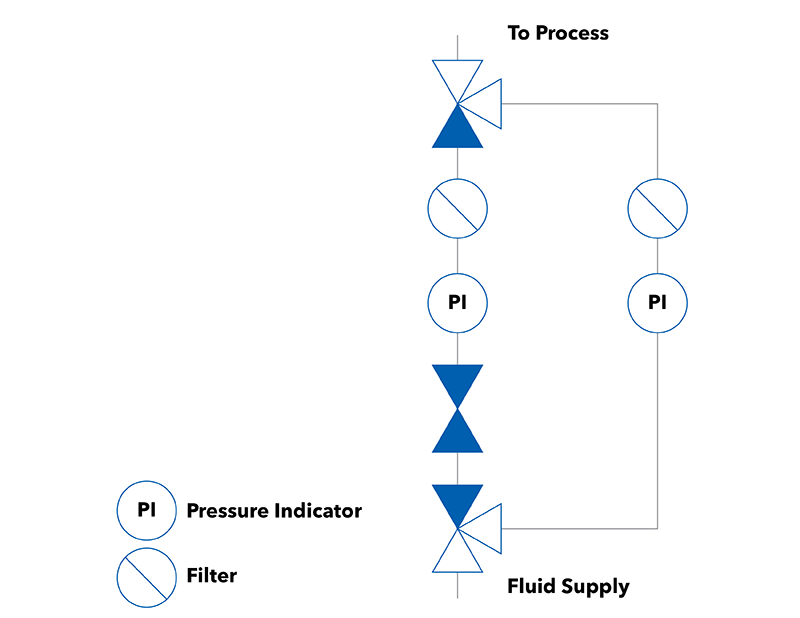
Figure 2. A bypass loop used to isolate a fluid system line allows the process to continue functioning while performing maintenance.
There are some additional benefits to this configuration. For example, the first block valve may be a three-way valve that can divert flow around the section being serviced, permitting fast filter changes, for example. For this reason, a bypass loop is an excellent choice in cases where downtime is not an option. Bypass configurations also help avoid water hammer issues that can result when a sudden system flow shutoff occurs.
Valve Selection
It is not just the system design that counts. Quality valves are critical for safe, successful isolation. A good valve should not leak across the seat, but leaks may inevitably occur due to environmental conditions or poor valve selections.
For example, if the line is located outdoors, the sun may heat the line, raising interior pressure beyond the block valve’s specified rating. Challenges can also arise if the block valve itself has not been properly maintained over the course of its life or if the wrong valve has been chosen. These reasons contribute to why a second block valve is necessary in designs, along with a vent or bleed valve.

Figure 3. A typical ball valve.
In most applications, there are two common choices for block valves for use in instrumentation lines: ball valves and needle valves.
Ball valves (Figure 3) deliver quick shutoff and high flow, while their handles provide helpful and clear indication of directional flow and shutoff. That quick shutoff in a DBB configuration, however, can lead to water hammer – a hydraulic shock caused by sudden flow stoppage that may result in damage to sensitive system components like pressure indicators, flow meters, and more.
Water hammer is mitigated when using a bypass loop. Before closing the first ball valve, the bypass loop is opened so the flow has a place to go, which prevents the sudden flow stoppage and pressure spike that would otherwise result.
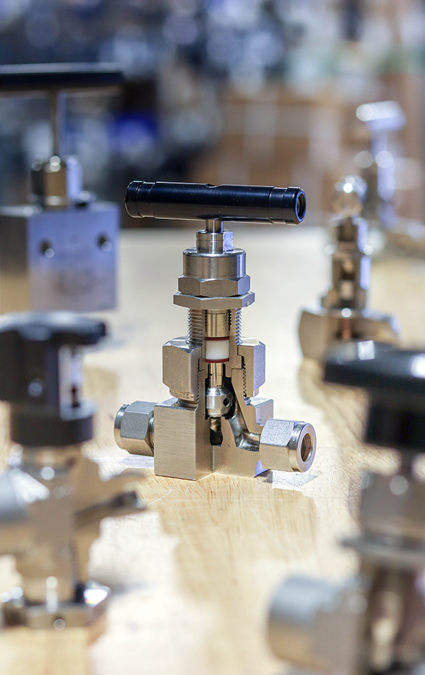
Figure 4. A typical needle valve.
Needle valves (Figure 4) are not susceptible to water hammer issues and are primarily designed for flow or metering control. They are also effective at positive, gradual shutoff. If used as a block valve for isolation, a needle valve should incorporate a rotating tip or soft stem tip, with special design considerations to ensure no leakage occurs during operation. For example, a metal V-tip needle valve can cause scoring of a metal seat during shutoff, compromising the seal.
Be cautious of inadvertently using the improper valve isolation configuration. Most ball valves and some types of needle valves are made for positive shutoff, but regulators are not. If a shutoff is required around the location of a regulator, the safest option is to install an upstream ball valve.
Beyond these two common options, there is a third option. Integral DBB valves (Figure 5; see top) feature a single valve incorporating internal double-block-and-bleed functionality, providing additional reliability with fewer possible leak points. These integrated valves further help reduce space and weight and can simplify installation for operators.
Finally, after selecting the right valve, it is good practice to install a pressure indicator downstream from the second block valve within an isolation configuration. This enables a quick visual check on pressure whenever maintenance is required.
Proper Isolation for Safer Fluid Systems
Isolating a fluid system line for maintenance activities not only results in safer plant operations but can help boost uptime, reliability, and ultimately, plant profitability. Technicians performing maintenance should therefore have a good working knowledge of isolation configurations and block valve selection to deliver the results refineries depend on.
Joe Bush is Swagelok Product Manager, Valves. An original version of this article appeared on the Swagelok Reference Point blog here
Print this page