Nonincendive electrical equipment for use in Class I, II and III, Division 2 hazardous (classified) locations
By Steve Czaniecki, Product Safety Engineer, Endress+Hauser Level+Pressure
Features E+H Electrical instrumentation ippt nonincendiveA Case Study of the history, design basics and installation of Division 2 Instrumentation in North America
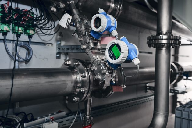
Photo courtesy of Endress+Hauser.
Introduction
The term nonincendive has long been associated with equipment designed for use in Division 2 hazardous locations, but what does it really mean?
As it applies to electrical equipment it simply means the equipment is not capable of igniting an explosive atmosphere by arcing or thermal effects under normal operating conditions. As simple as this sounds, there exists lots of confusion around the term nonincendive as it can be applied not only to equipment, but also to circuits, field-wiring circuits, components, field wiring apparatus and associated field wiring apparatus. While the basic definition of not being ignition capable under normal operation applies to all, how it is applied to each does differ and it impacts how the equipment must be installed. This will be explained as we explore the requirements for Division 2 equipment.
Background
Around 1950, it was determined that not all areas of a hazardous location involved the same high level of risk. The US National Electrical Code (NEC), and soon after the Canadian Electrical Code, Part I (CEC) then divided hazardous locations into two distinct areas, Division 1 and Division 2. In a simplistic form, Division 1 included the same high-risk areas where an explosive atmosphere could be considered likely to exist most of the time. Division 2 locations were to include areas where an explosive atmosphere would only exist under abnormal conditions such as the failure of a containment or ventilation system. Since the hazard only existed in Division 2 under abnormal conditions, it was determined that equipment installed in the area no longer needed special protection such as explosion-proof housings.
Instead, the general practice in North America was to allow industrial quality general-purpose equipment to be installed in Division 2 locations if it contained no arcing parts or high temperature surfaces when the equipment was operated in its intended manner. The premise of this is that the risk of ignition required not only a fault of the containment or ventilation system to create a hazardous atmosphere, but also a fault within the equipment where a spark or high temperature could ignite this atmosphere. Therefore, if the equipment contained no arcing components or high temperatures when operated normally, it was not considered to be a source of ignition of the hazardous atmosphere that may exist for a short period of time.
Over the years as equipment became more complex, it was more and more difficult to determine if these basic criteria could be met. As a result, the first product standards specific to equipment for use in Division 2 hazardous locations were developed in the 1980’s. In the US, the standard was UL 1604 (first published in 1984) and in Canada the standard was C22.2 No. 213 (first published in 1987). Over the years, these standards have gone through many developmental changes and today there now exists a harmonized US/Canadian Bi-National standard: UL121201 / CSA C22.2 No. 213 – Nonincendive electrical equipment for use in Class I and II, Division 2 and Class III, Divisions 1 and 2 hazardous (classified) locations.
Design and Construction Requirements of UL121201/CSA C22.2 No. 213
General
The basic presumption of the standard is that the equipment being evaluated as nonincendive may be powered by and/or contain circuits that have enough energy to be incendive; meaning they could potentially ignite a surrounding explosive atmosphere by spark or thermal effect produced under normal operation. Therefore, additional design requirements may be necessary to mitigate the risk of an explosion.
Thermal Effects
To evaluate thermal effects, the equipment would be operated as normally intended, but done so considering the worst-case supply and loading characteristics that will produce the most heat. Temperatures are measured on all internal and external surfaces to determine the maximum surface temperature of the equipment. This temperature is then marked on the equipment either by direct value or by the applicable temperature code rating which allows the user to determine if the equipment is suitable based on the minimum ignition temperature of the potential explosive atmosphere that may be present. For functionality, most process instrumentation will not operate properly if producing such high temperatures, so rarely will the thermal effects create a non-compliant piece of equipment.
Arcing and sparking
Of more concern, is the effect of a normally arcing component in what could be considered an incendive circuit. It is very simplistic to state that only equipment which produced no sparks should be considered suitable for Division 2 applications. However, this would be very limiting for the types of equipment that could be used as most industrial and process control equipment contain components that would be considered normally arcing. Some examples of normally arcing components are switches, relays, connectors, plug-in components, circuit breakers and potentiometers. For this reason, several techniques were developed to help mitigate the risk of ignition from these normally arcing components that may be installed in Class I, Division 2 locations. These are described briefly below.
Nonincendive Circuits
While it is considered in most cases that the equipment is powered by an incendive circuit, the internal circuitry that contains many of these normally arcing components has likely been reduced in voltage and current levels such that in normal operation the energy levels are no longer incendive; in other words, considered a “nonincendive circuit”. So even if a spark is created by a normally arcing component in this type of circuit, it would not be ignition capable. The determination of a nonincendive circuit is based on the intrinsic safety protection method, with the difference being that no faults or additional safety factors are considered to maximize the available energy (i.e. only normal operation is considered). The evaluation of a nonincendive circuit involves determining the maximum voltage and current in the circuit, as well as the potential energy that may be discharged by the circuit capacitance and inductance. To determine compliance, these parameters can either be compared to the published ignition curves (included in the standard), or by actual testing using a spark ignition test apparatus.
Normally Non-arcing Components
As an alternative to conducting a nonincendive circuit evaluation, or where a circuit cannot meet the conditions for a nonincendive circuit, make/break components can be considered “normally nonarcing” in normal operation if they meet certain criteria.
Most commonly, this applies to connectors and plug-in components. When used in an incendive circuit, these components can be considered normally nonarcing if connection or disconnection is not required under normal operational conditions and, either the connection is secured with a mechanical retaining device (which does not rely on friction alone), or a separating force greater 15 N is required to cause disconnection.
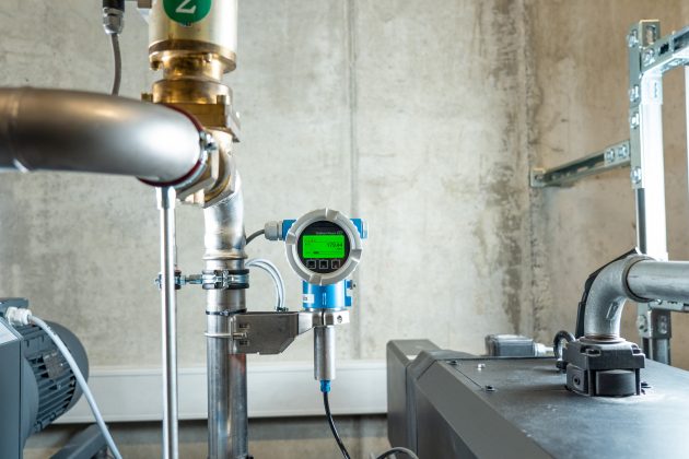
Photo courtesy of Endress+Hauser.
For plug-in components that weigh less than 30 grams, it is only required that they withstand a pull test using 3 times the weight of the component. If the connector or plug-in component is accessible during normal operation, then additional warnings are required to advise the operator not to disconnect the connector/component unless the power has been turned off or the area is known to be non-hazardous.
For plugs and sockets used on the exterior of the equipment, additional precautions are required. The connection must be tool secured, a warning is required to specify not to connect or disconnect while the circuits are live, and the connector/plug must accommodate only specified cables that are permitted by the NEC or CEC, Part I (as applicable).
Manually operated make/break components that are located such that they are only accessible by use of a tool can also be considered as normally non-arcing.
Nonincendive Components
For other components such as switches and relays that are used to make/break incendive circuits, there are additional techniques that can be used to determine their suitability of use in nonincendive equipment. One such technique is to evaluate the component as a “nonincendive component”. The premise here is that the contact configuration is large enough to absorb most of the energy generated by the spark such that there is not enough energy left to ignite the surrounding explosive atmosphere. The only way to evaluate such a component is by test. The test involves placing a pre-conditioned component in a test chamber filled with a test gas specified for the gas Group for which it will be marked. It is ensured that the component housing will not impede the gas from direct contact with the switching contacts and then the component is operated a minimum 50 times while connected to the maximum rated load. If it can be shown that the contacts do not ignite the surrounding explosive gas atmosphere, then the component is considered to meet the definition of a nonincendive component.
Enclosed-Break Device
Similar to the nonincendive component, another technique is to evaluate a component as an “enclosed-break device”. This method also presumes that the explosive atmosphere surrounds the contacts, but in this case, it may be ignited by the spark created when switching the maximum rated load of the component. The protection is by virtue of the component housing such that it is designed to withstand this small internal explosion and prevent it from propagating to and igniting the atmosphere surrounding the component housing. This loosely follows the idea that the component housing is similar to an explosionproof housing without all the construction requirements. To evaluate these types of components, they are first artificially aged and then subjected an ignition test where the component is switched 10 times in a chamber filled with the appropriate test gas mixture.
Sealed Device
Another technique that can be used to allow components such as switches and relays to make/break an incendive circuit is to evaluate the component as a “sealed device”. The premise here is to prevent the surrounding explosive atmosphere from entering a sealed space around the contacts. If the contacts are hermetically sealed (e.g. by means of welding, brazing, soldering or the fusion of glass to metal), then the component is considered to meet the definition of a sealed device without further testing. Components can also be sealed by use of gaskets or an encapsulated seal, but in this case the integrity of the seal must be proven by an air leakage test.
Class II and III, Division 2
The assessment of nonincendive equipment for use in Class I, Division 2 location focusses on minimizing the risk of ignition by a spark or thermal effect while assuming the hazardous gas atmosphere is in direct contact with the internal components of the equipment. The assessment for nonincendive equipment for Class II and III, Division 2 locations differs in that it focusses primarily on keeping the hazardous dust atmosphere from entering the equipment. Therefore, the equipment can safely have internal sparking components in incendive circuits since they are not in direct contact with the hazardous atmosphere; much like the premise behind sealed devices. The concern of thermal effects is also shifted from maximum internal surface temperatures to the maximum external surface temperature of the enclosure.
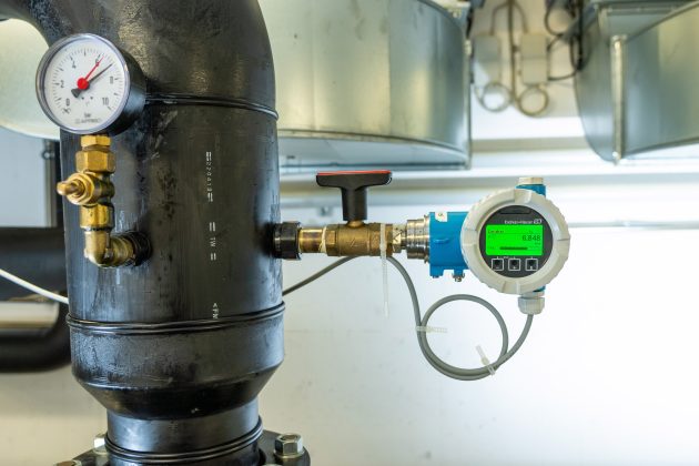
Photo courtesy of Endress+Hauser.
The standard allows several methods to validate the ingress protection of the equipment housing. These methods include meeting the dust-tight requirements or requirements for a Type 4, Type 4X, Type 6, Type 6P housing in accordance with standards UL50 / CSA C22.2 No 94.1 and UL50E / CSA C22.2 No. 94.2, or by passing a dust-blast test, circulating dust test, or atomized-water test as prescribed in the standard. Equipment or components that meet the requirements for a sealed device would also be allowed.
The standard also includes an option to forego the exclusion of dust from the internal components, but only for nonincendive circuits with the additional consideration that the entrance of dust can cause shorting of components and traces and can accumulate on the internal components. This must not result in an ignition due to spark or charring of the dust due to heating.
External Field Wiring
All of the above nonincendive protection techniques presume that any external wiring connected to the equipment (e.g. power, signals, loads) are incendive circuits. To ensure this external wiring is prevented from being a source of ignition due to potential mechanical faults, both the NEC and CEC, Part I specify certain types of wiring methods that must be followed when installing the equipment in a Division 2 location. These methods provide adequate mechanical protection to minimize the possibility of opening, shorting, or grounding of the incendive wiring.
Nonincendive Field Wiring
The NEC and CEC, Part I also provide an exception to the specified types of Division 2 wiring methods when these external field circuits are identified as “nonincendive field wiring.” In the case of nonincendive field wiring, normal operation now includes the possibility of the wiring being opened, shorted or grounded without creating an ignition capable spark. As with the evaluation for internal nonincendive circuits, it is based on the intrinsic safety concept without additional faults or safety factors applied. Since it is shown the wiring is not ignition capable under these conditions, the Codes provide an exception to using the standard wiring methods that provide mechanical protection. Therefore, nonincendive field wiring offers the benefit of being able to utilize less expensive types of ordinary location cables; however, the drawback is that all equipment that is to be connected must be specified. This is the only way that it can be determined how much resistive, capacitive and inductive energy is available in a spark that may be created by opening, shorting or grounding the interconnecting wiring. Equipment that is connected to nonincendive field wiring is defined as “nonincendive field wiring apparatus” and it must provide a statement in the markings that it is for connection to nonincendive field wiring circuits. It must also clearly identify the terminals used to connect to these circuits and either specify what devices can be connected or provide parameters for the maximum voltage and current that can be connected to these terminals, as well as the maximum capacitance and inductance that is potentially available at these terminals. The equipment that supplies the power to the nonincendive field wiring is defined as the “associated nonincendive field wiring apparatus”. It is required that this equipment specify that it provides nonincendive field wiring circuits and specify the parameters for the maximum output voltage, short circuit current, and maximum capacitance and inductance that can be connected to its terminals. Based on the specified parameters for each of these devices the user can determine if the two devices can be connected and create a nonincendive field wiring circuit. Details of the conditions that need to be met as well as other critical installation information would be specified on the manufacturers Control Drawings which would be referenced on each of the equipment’s marking nameplate.
It should be noted that that only a small percentage of nonincendive equipment would be approved only as nonincendive field wiring apparatus which requires the use of nonincendive field wiring. More common would be to offer connection to nonincendive field wiring as an alternative installation method. This gives users the option to install either with the standard Division 2 wiring methods or use the exception of ordinary location type cabling together with the use of associated nonincendive field wiring apparatus. There are also certain instances where it is required for equipment to be connected to nonincendive field wiring as the sole means of protection. This is typically the case for small sensors that do not have provision for connection of one standard wiring methods specified for Division 2, and therefore the only option is to connect with nonincendive field wiring.
Another common application for nonincendive field wiring would be for the interconnection of external components of a known system (e.g. a transmitter housing and a remote sensor). In this type of system, the interconnecting wiring might not be one of the specified Division 2 wiring methods; however, it could be determined to be nonincendive field wiring since both ends of the connections are known and can be assessed as part of the approval.
Is it really that simple?
By using one, or any combination of the above nonincendive techniques included in the UL121201/CSA C22.2 No. 213 standard, equipment can be approved and marked for use in Division 2 hazardous locations. One area that tends to cause some confusion is that users expect to see the equipment identified specifically as Nonincendive, or it’s abbreviated designation NI. Unfortunately, this is not always the case as it is not a requirement of the standard that the equipment be marked with this designation, nor is it a Code requirement that Division 2 equipment be designated as nonincendive. The confusion is created in part because some approval agencies insist that Division 2 equipment include the Nonincendive (or NI) designation, while others either do not require it or do so inconsistently. So, the same equipment that has been assessed to the same requirements may or may not be marked as being nonincendive, dependent on the Certifier of the equipment; no wonder it’s confusing. What is important to note is that the NEC and CEC, Part I only require the equipment be marked with the applicable hazardous location designation where it may be used. Therefore, if it is approved to the requirements of UL121201/CSA C22.2 No. 213 it will be marked for the applicable Class I, II or III, Div. 2 location. So even if it doesn’t specify it, you can be assured the equipment is still nonincendive when it meets the requirements of this standard.
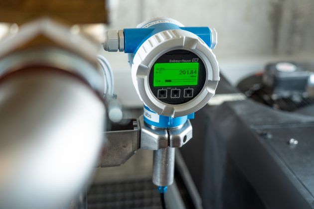
Photo courtesy of Endress+Hauser.
Another area of confusion regards the issue of nonincendive field wiring and the method of installation. As noted previously, the majority of nonincendive equipment is approved without nonincendive field wiring and therefore must be installed using one of the permitted wiring methods in accordance with the applicable Code. For nonincendive field wiring apparatus, it is not always made clear to the user that this is the case. Sometimes a reference to a Control Drawing is the only indication that nonincendive field wiring may be involved and that certain conditions regarding the use of associated nonincendive field wiring apparatus is required. Even more confusing is the scenario where nonincendive equipment may use nonincendive field wiring as an alternate installation method, or where only certain terminals must use nonincendive field wiring. This information is not always apparent on the device markings and again the user must pick up on the reference to a Control Drawing where all this information will hopefully be detailed in a clear manner to ensure the proper installation.
Conclusion
Given that an estimated 90 per cent or greater of all hazardous locations in North America are classified as Division 2, this is an important industry segment and the use of equipment specifically approved for Division 2 offers great cost benefits in both the equipment and installation methods. With the UL/CSA bi-national standard for Division 2 equipment, requirements are now harmonized for the North American approval of nonincendive equipment which helps manufacturers get products to market in a timely and cost-efficient process. But to take better advantage of these benefits, manufacturers need to continuously improve on the product information, markings and Control Drawing information to help users fully understand the scope of the Division 2 approval so that the proper equipment can be chosen and installed safely. It would also be beneficial for users to have a better understanding of the nonincendive protection technique and installation methods that are used for Division 2 so that they can ask more informed questions and make more informed decisions on equipment choice and application. The goal being to make the use of Division 2 equipment a simple process and not make it more complicated than it needs to be.
About the author: Steve Czaniecki is a Product Safety Engineer with Endress+Hauser Canada Ltd. He has over 30 years’ experience in the design and approval of process instrumentation for use in Hazardous (Classified) Locations.
Print this page
Advertisement
Stories continue below
Related