Understanding the critical factors for accurate temperature measurement
By Frank Liebmann, Metrology Engineer, Fluke Calibration
Features emitted Fluke Calibration infrared IR thermometer radiation Temperature Infrared thermometers measure temperature by detecting the
thermal radiation emitted by an object’s surface.
Infrared thermometers measure temperature by detecting the
thermal radiation emitted by an object’s surface. Temperature is one of the most pervasive elements in today’s process, industrial and commercial environments.
Infrared (IR) thermometers measure temperature by detecting the thermal radiation emitted by an object’s surface. The infrared energy measured by the thermometer is filtered by its optical system, which is only sensitive to a specific spectral band — typically 8 to 14 µm (microns). Because these thermometers don’t contact the surface of the object they are measuring, they are ideal for applications involving running equipment, very high temperatures, high-voltage, or difficult to reach components.
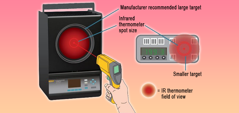
The optical scatter of an infrared thermometer makes it necessary to use large targets for many calibrations.
However, as the demand for infrared thermometers has grown over the years, so has the concern about the accuracy of their measurements. A closer look reveals that much of that concern can be alleviated by increased knowledge of how to use IR thermometers correctly and how to ensure that they are accurate.
The need for standards
To give a little history, in November 2008, the ASTM Subcommittee E20.02 on Radiation Thermometry discussed the need for new standards governing the selection, use, and calibration of IR thermometers. Those discussions led the subcommittee to proceed with developing two new international standards.
The first — E2758 – Standard Guide for Selection and Use of Wideband, Low Temperature Infrared Thermometers, initially approved in 2010 — addresses the concerns of IR temperature measurement error in the field.
The second — E2847 – Standard Test Method for Calibration and Accuracy Verification of Wideband Infrared Thermometers, adopted in 2012 — establishes guidelines for verifying the accuracy of IR thermometers traceable to the International System of Units (SI) unit of temperature, the kelvin (K). Both E20.02 standards were applied in common practice shortly after adoption and continue to be updated.
Essential factors affecting accuracy
The primary reason for developing these standards was the committee’s assessment that many of the errors in IR temperature measurements resulted from a lack of understanding of the factors that impact accurate IR temperature measurement. Some of the most common factors that need to be understood include:
Emissivity
Emissivity is one of the largest causes of error in infrared temperature measurement and varies widely according to the type of surface being measured. Understanding it is critical to obtaining accurate IR temperature measurements. Emissivity values range from 0.00 where no energy is radiated — to 1.00, where the surface radiates perfectly at all wavelengths. This latter example, called a “blackbody”, is an ideal surface that absorbs all incident electromagnetic radiation at all wavelengths and radiates all infrared energy according to Planck’s law. A general rule is that reflective surfaces are less emissive than dull surfaces. So oxidized metal surfaces are more emissive than shiny polished surfaces, and painted surfaces are more emissive than either.
It is important for users to know the emissivity of the surface so technical staff can adjust the IR thermometer’s emissivity setting to compensate. There are many ways to determine emissivity. Some of the most common include:
- Emissivity tables: Typically provided in the IR thermometer user manual or from a technical source.
- Comparison: This involves comparing measurements of a surface with a coating of known emissivity to an uncoated portion of that surface with an unknown emissivity.
- Contact versus Non-Contact method: The emissivity on the IR thermometer is adjusted until the readout matches the readout for the contact thermometer.
- Blackbody test method: This is a destructive method where a hole is bored into the object being measured. The bored hole has an emissivity close to 1.00 which is compared against the rest of the surface.
- Fourier Transform Infrared Testing: This is a laboratory method where reflectivity is measured over a wide spectral bandwidth, and emissivity is inferred from the reflectivity.
Since perfect emissivity is not physically possible, a near blackbody with known emissivity that radiates as close to 1.00 emissivity as possible is used as a radiation source to calibrate IR thermometers.
Distance-to-size ratio
Virtually all IR thermometers include a “distance-to-size” ratio (D:S, sometimes referred to as distance-to-spot ratio) in their specs; but not all users understand how that value affects measurement accuracy. The distance-to-size ratio indicates the area being measured at a set distance from the target. So, a 12:1 D:S ratio means that the IR thermometer measures a 25 mm diameter spot from 300 mm away. This ratio is used to guide the distance from which to make infrared temperature measurements for that specific thermometer.
Increasing the distance beyond the specification reduces accuracy because the increased distance expands the measurement area, which may bring in temperature measurements outside the area targeted. IR thermometers are available with D:S ratios ranging from 1:1 for the lowest priced models to 60:1 for high end models.
Role of the laser pointer
Most IR thermometers include laser pointers which make it easier to identify the general area the thermometer is measuring. However, there are some misconceptions about what the laser does. It does NOT measure temperature; it simply points to the target to indicate a part (sometimes a very small part) of the area being measured.
Along the same lines, there is a common misconception that the area measured by an IR thermometer is limited to the small point at the end of the laser pointer. The laser pointer is just a guideline that gives the user a center point for the area being measured. The actual size of the bulk of the area measured is determined by the spot size in the thermometer’s D:S ratio.
Traceability is key
Proper calibration with an unbroken chain of traceability to the SI is the only way to ensure IR thermometer accuracy. Labs that calibrate IR thermometers use several levels of calibrators, all of which must be traceable by calibration to the level above.

Accurate IR thermometer calibration involves more than just pointing the thermometer at the radiation source and recording the temperature.
At the top level in a calibration lab are primary reference standards. Primary standards are sent out to certified primary standards labs to be calibrated against standards established by national metrological institutes like the National Research Council of Canada (NRC) Calibration Laboratory Assessment Service (CLAS). This establishes an unbroken chain of traceability from the primary standards to the SI unit of temperature (K).
The primary standards are used to calibrate transfer standards, which are then used to calibrate the reference radiation source (blackbody device). A blackbody is approximated in the lab by a device that has a large cavity with a small opening. Any light entering the small opening is reflected off the walls of the cavity multiple times preventing reflection and delivering near perfect emissivity.
A few tips for calibration success
Accurate IR thermometer calibration involves more than just pointing the thermometer at the radiation source and recording the temperature. Environmental elements, including ambient temperature and humidity, must also be monitored. The radiation source shouldn’t face a window or be located near an air vent. Equally important is how the thermometer is positioned.
The distance of the thermometer to the target must be measured to ensure that it matches the thermometer’s D:S ratio. And, because IR thermometers have optical scatter, it’s important to know the field of view, which specifies the area beyond the target spot size the thermometer is measuring. This can account for from 1% to 35% of the total measured energy of an IR thermometer.
So, although the 25 mm spot size indicated by the D:S ratio may be adequate for field measurements, it doesn’t provide the level of accuracy required for proper calibration. As a result, the target used to calibrate an IR thermometer should be significantly larger than the size indicated by the thermometer’s distance-to-spot ratio.
Documenting the details
All calibrated IR thermometers should return with a detailed calibration report. The report should clearly identify the device calibrated, and the date of calibration. In addition, it should include data that addresses all the variables that affect accuracy, including:
- Source temperature versus infrared thermometer readout temperature
- Measuring distance
- Emissivity setting of the infrared thermometer
- Diameter of the radiation source
- Ambient temperature
- Description of the aperture including aperture distance (if used)
- Measurement uncertainties
- Description of the calibration procedure
- List of reference instruments
- Traceability statement
- Description of the uncertainty budget for all the calibration equipment and the IR thermometer being calibrated
This information sets a benchmark, so the conditions can be duplicated each time the thermometer is calibrated, helping to ensure consistent accuracy throughout the life of the device. Understanding the variables that contribute to potential inaccuracies in IR thermometer measurements, can improve the ability to overcome them and increase confidence in this very valuable temperature measurement method.
Frank Liebmann, Metrology Engineer, is with Fluke Calibration.
Print this page